I see alot of trikes out there that have the gear lever poking out the side of the seat area or between the drivers legs etc and personally i don’t like either method so decided that due to my trike being a auto i can hook it up to a pedal by my left hand foot. I’m not convinced i like the look of this particular pedal pictured here but its functional. It operates a morse cable which pushes and pulls the gear selector linkage at the transmission.
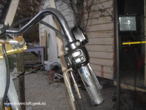
What i’ve done here is taken the orginal selector lever from the Honda Inspire and shortened it to hide behind the panel of the trike. I’ve also tack welded the original shifter gate to a peice of 3 mm plate and then mounted a electrical solenoid to the side of it so that when i flick a switch on the handlebars it pulls the lock pin down which then allows me to shift it out of gear. When i let go of the button on the handlebars it then pushes the pin back in place and locks it in gear.
This is still a mock up version of how i’ve set up the rear brake system. As mentioned previously any part of the braking system that is welded must have a ND certificate, so what ive done is machined up a pivot system out of a solid round bar so that nothing is welded. The pivoting item pictured in the middle of this picture has two bearings in the middle of it to allow free and easy pivoting action of the top bracket
On the right hand side i have the brake pedal, which connects to a 19mm brake pedal shaft which spins inside bushes. On the other end of the brake pedal shaft i have a one peice bracket machined out of round bar that will be bolted and locked to the shaft by a roll pin or grub screw etc so that nothing is welded. Coming off that bracket i have drilled a hole 1 inch off centre ( because the distance from the brake pedal shaft to the foot rest of the brake pedal is 6 inches therefore giving me a pedal ratio of 6:1). Bolted through that hole i have a rod with two rose joints either end that connect to the pivot system which in turn connects to the master cylinder. After bleeding the system up the pedal travel was a little excessive at a ratio of 6:1 so the bracket on top of the pivot has multiple holes in it which i can play around with till i have the correct feeling brakes ( which i won’t know untill i get the front forks made so i can test drive it) but for now the pedal travel is spot on , as for efficency i’ll have to wait and see.


