Here’s where i see the second immediate cosmetic issue. If i was to go with the idea of using the whole front end including suspension then i would end up with the top arms poking above the wheel like they do here, so for now i see i have a couple of choices. 1) use this set up anyway and save alot of time and money cause i wont have to re make all the suspension etc individually and then hide the top arms with the body panels or something or.. 2) re invent the wheel so to speak by designing and making my own custom suspension and subframe which in return would be a long process and cost large amounts of money just so i can make the rear suspension look tidier yet function the same … hhmmm think i know what i’ll pick.
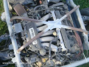
I’m starting to make up a frame jig out of a long length of I beam and a long length of C channel and placed the motor on it. Even though the jig is pictured here sitting on the ground it is in fact level in all directions :-). Anyway I’ve put the motor in place on the jig and welded the box section ( labeled 1) square to the jig and then welded #2 to the box section just to give me a little clearance, I then tack welded the silver tubing to the front of the subframe so that i can now shift the motor hard up against the box tubing and i’ll then know that the motor is sitting square to the jig
I tack welded a metal plate to the frame jig then marked out the centre line for the jig ( arrow points to that) and then i placed a laser level so that the laser ran up the line i just marked out and then i was able to shift the motor around so that the laser beam ran straight up the centre of the motor/subframe assembly. ( you may need to click on the photo to see the line that the laser made). Tomorrow i will weld on some brackets to the frame jig then bolt the subframe to the jig so that the motor stays in line and doesn’t shift whilst i’m working on it.


