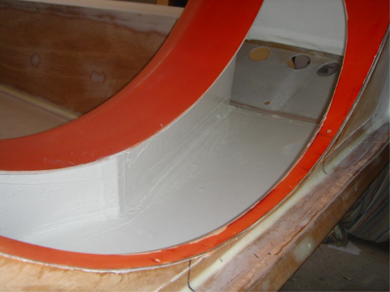
This is one of my air diverter panels finally put in place. The panels i fitted here are in a V shape and go from the rear corners of the cockpit to the center, i done it like this so that rather than the air entering the plenum chamber and collecting under the front of the duct then bouncing of the flat rear cockpit panel it will hopefully hit this V shaped panel and have a bit more positive guidance to the side plenum chambers.
This is what i call my rear air diverter panel, what i have done here is pretty much blocked off the holes in the rear panel so that when the air enters the plenum chamber it will try to go around the craft first before trying to escape directly out the rear holes. I was going to extend this panel around the rear corners so that the air was immediately directed down the sides of the craft but then decided that considering Kens craft that i seen, had no air diverter panels at all yet still operated fine, leaving the rear corner holes open may help assist in lifting the heavier back end . That’s my thoughts anyway weather they are right or wrong, no turning back now anyway cause its all fibre glassed and painted. The ends of this panel are not closed off and when the plenum chamber builds up pressure then the air will still be able to exit the rear holes, they are just highly restricted
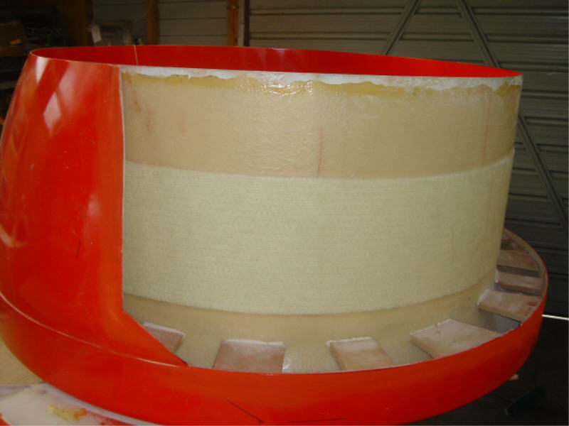
Forgot to add this photo of cutting into the duct
Once i cut part of the shell off the duct so that it fits in the craft i then used the fibre glass that i cut out to add the strength back into it. Once this is fitted to the craft this section is not viewable so i didn’t go overboard with tidying up the fibre glass , i just painted over it.
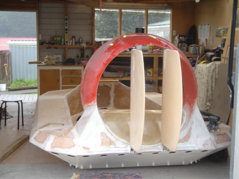
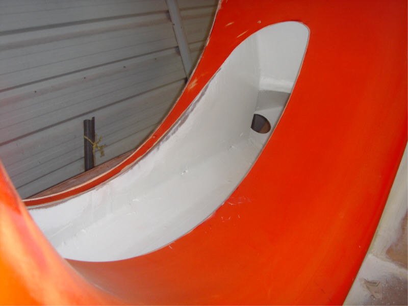
Finally its back on the ground again, just got a few spots to fibre glass on the inside of the duct and then i can move onto the mechanical side for now and get the fan assembly fitted. The rudders are now fitted and pivoting smoothly, wooo hooo the first mechanical section of my craft and it works hehe.
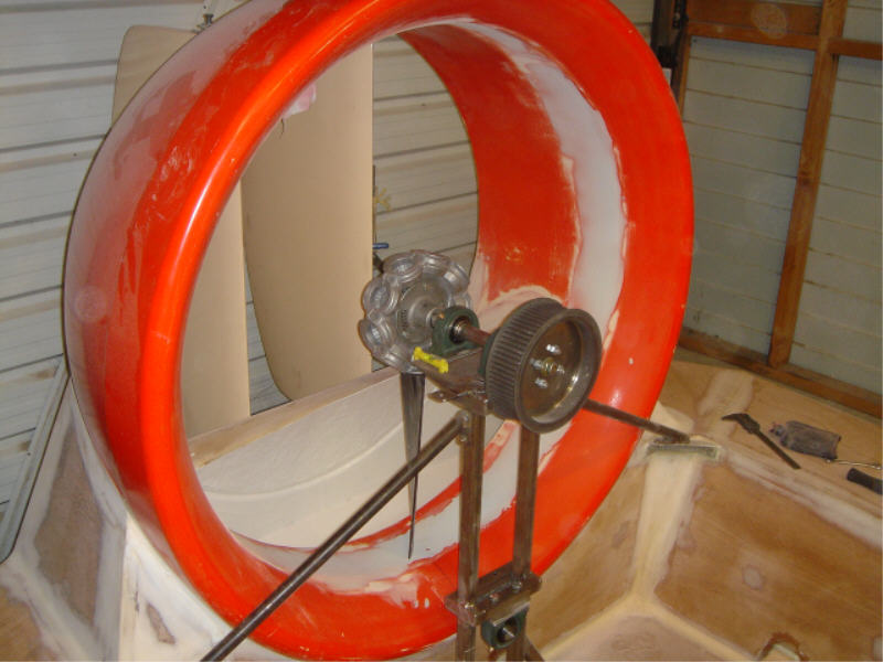
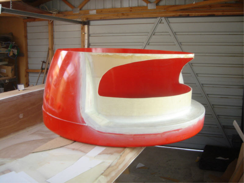
This is my attempt at making the duct round. Before i started there was at least 4 to 5 mm difference between tip clearance at certain spots of the duct, so i came up with the idea that if i put masking tape around the tip of ‘one’ blade then add Q cells to the duct and spin the blade it should in theory spread the Q cells around relatively even to take up spots that had excess clearance. The thought was there but it didn’t quite work the way i thought it would , but it wasn’t too bad , tip clearance is now, at worst, 1.5 to 2mm larger than other areas. Just have to sand it all down smoothly now.