I’ve made up some bosses to support my gears to the fan and crank shafts. They have been made up in a lathe and have keyway’s down the centre of them. Now that i think about it , it probably would of been easier to make them tapered in the centre rather than muck around with a key way but i’m not concerned , at least i know its done right.
This is the gear at the far end of the crank shaft

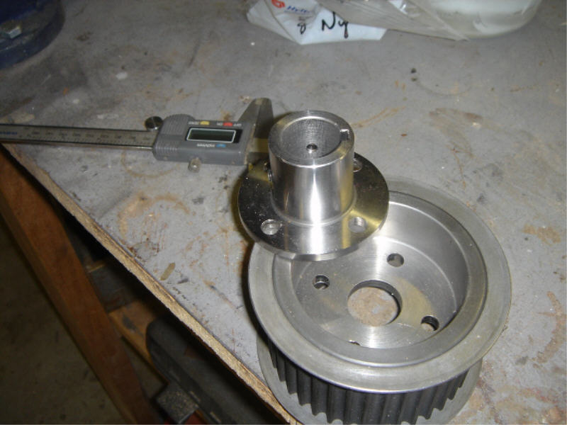
Here’s the gear for the Fan shaft. Both this gear and the crank gear have keyway’s cut into them and also both have a couple of grub screws fitted. I’m not totally happy on relying on just grub screws so i’ll probably fit some aluminium spacers between the bearings and the gear and fan bosses, that way the load is taken off the grub screws when i add a bolt to either end of the shaft. Time will tell, i’ll worry about that later.
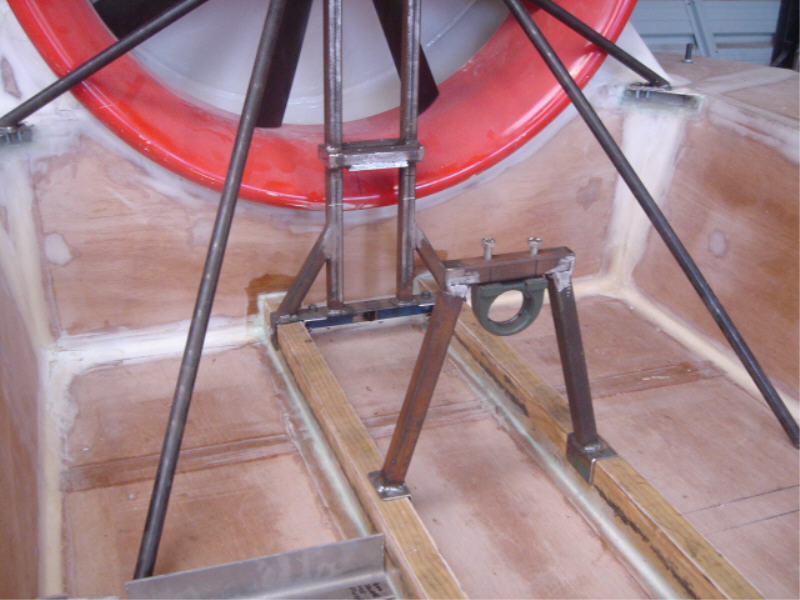
Because the subaru motor will be sitting alot further forward than i expected that will mean the shaft that will come from the rear of my flywheel will be probably around 1 meter or so long, therefore i made up another plummer/pillow block support that i will mount later so that both ends of the shaft prior to the drive coupling will be supported.

This is a side view of the drive train. I have shortened my fan frame in comparison to earlier fan assembly pictures on my site so that the plummer/pillow blocks now have two 5mm spacers placed under each one. That way if at any stage my craft starts to distort with age things are adjustable. You can see the spacers I’ve made from aluminium under each bearing block.
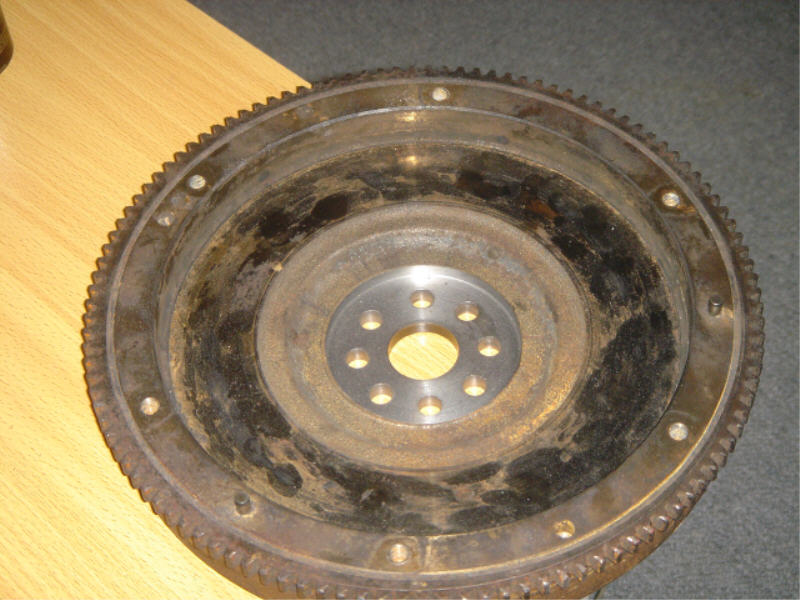
The flywheel is the original EA82 flywheel and i’ve machined the center (the silver section in this picture) out by 8 mm so that the boss that i’m making for it will locate it self into the machined hole. i did this for a couple of reasons. 1) So that it stays sitting nice and central and 2) so that i can use the original Subaru flywheel bolts without losing any of the length of thread that screws into the crank. Word on the street is that the thread that Subaru use for these bolts are hard to come by in a longer bolt, and when you do find some they are expensive, so i didn’t bother checking to see if that is true i just designed the new boss to use the existing bolts.
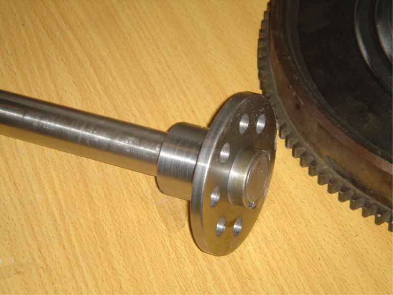
This is the boss that i’ve made up to fit neatly into the flywheel, the flange is 8mm thick it has a keyway cut into it and also fits snug into where the spigot bearing would usually be fitted. What i haven’t done yet is drill a hole completely through the shaft and boss so that i can fit a roll pin to it so that the shaft doesn’t go walkabout. 🙂