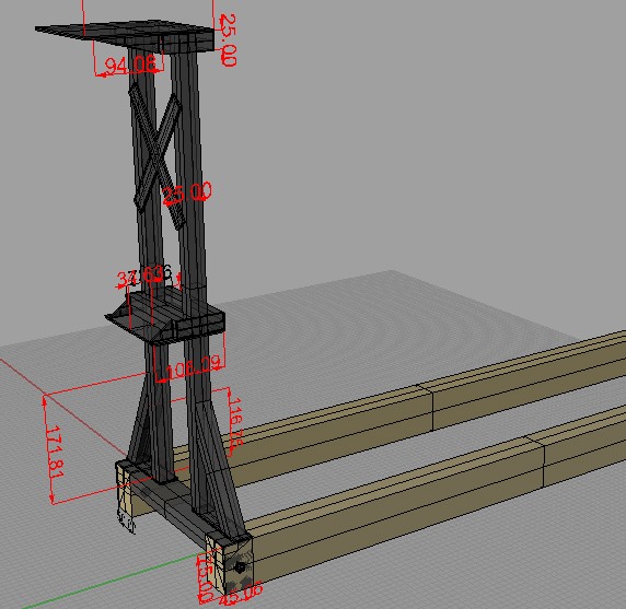
This is the idea i had for making the fan frame. I made this using a 3D Cad type program and as you can see i had no idea how to use it properly but it gave me a fair indication of what i wanted , and when i didn’t like something about the design it was easier to modify in this program than it would of been re cutting and welding extra metal. As a bonus feature i worked out how to draw it all to scale , so that meant all dimensions could be saved for later when it came time to cut the parts out 🙂
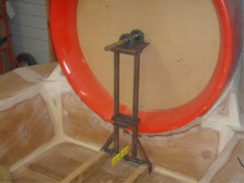
After making the idea up on computer i started building it from a mixture of 25mm box section and 4 mm flat plate and a scrap piece of angle iron. It’s yet to be finished but the general concept has been built. In the middle of the duct is a neatly fitted custom wood disc that was made using a nail, a length of wood and a router. It gives me the true center of the duct. from there i drill a 25mm hole in the disc so that my fan shaft can fit through it neatly so i can line up where the top plate of the fan frame will sit.
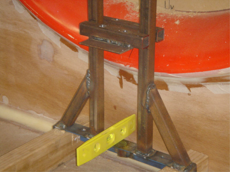
The lower half of the frame has some supports welded in place to spread the load of the upper section. The plate you see in the middle of it here is where two plummer blocks will be bolted to so that the shaft from my motor can be supported at both ends, i won’t weld them in place yet till i mount the motor roughly in place.
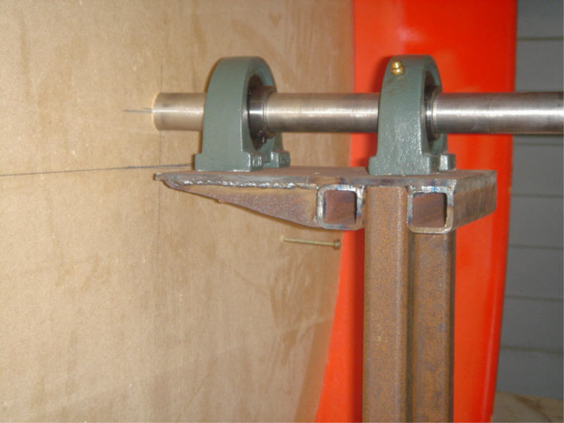
Here the upper section of the frame is shown and as you can tell i’m yet to finish this section. The top plate is yet to be welded in place and i have also got to block off the open ends. In addition to what you see pictured here and above i will be adding support bars to stop it from twisting sideways and also support bars to stop it from rocking backwards or forwards. The gears for my set up will hang off the end of the top and bottom plates, unfortunately i’ve run out of time again so that will have to wait till another day.
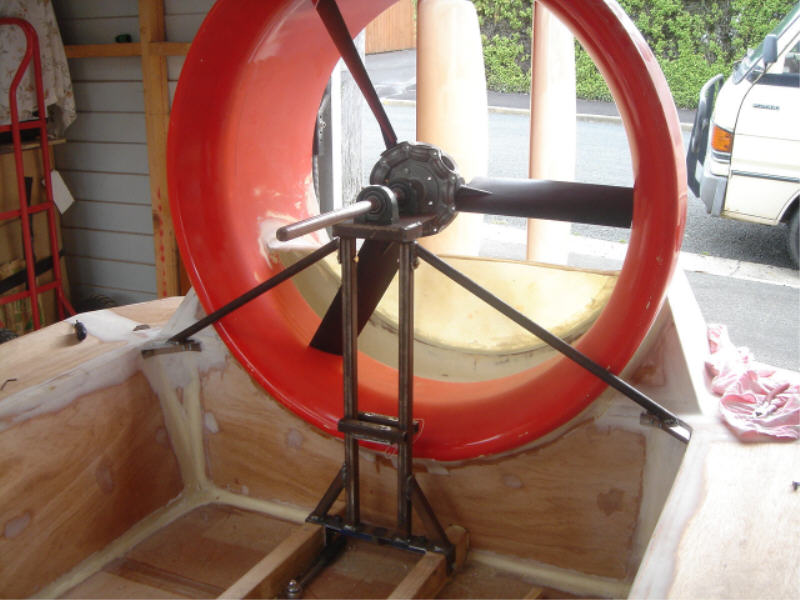
I have started to cut the 5ZL PPG blades to size and as you can see here i have done 3 of the 9 blades and then i just had to take a photo cause i was over the moon at how close i managed to fluke getting the fan central. After placing some shims under the top plummer blocks it works out that i was only 0.75mm (3/4 of a mm) off center, so I’m stoked about that. I have also made some side support bars for the frame and bolted them to some aluminum brackets that i have made in each corner of the craft. Next task is to make forward facing support bars but i got to make sure they wont hit the motor when fitted. At least now i can sit there and spin the blades by hand and make noises whilst i dream that its hovering hahah.
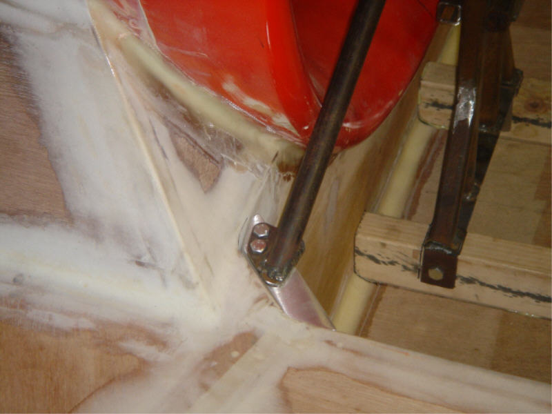
Made and welded up these aluminum brackets to fit into the corner of the craft (yet to be fiber glassed in permantly i’ll do that another day) so that the side support bars can be bolted to it.
Oh, and and and ……. did i mention that
i was only 0.75mm (3/4 of a mm) off center hehehe
(2 days after my above comment thinking i was clever for being so accurate . i now have to add this below comment)
UPDATED comment: Ok its just been brought to my attention that i shouldn’t of been so precise. So today’s tip is …. design a fan frame so that the bearing mounts are shimmed at least 10mm (not only 0.75 like mine) that allows for any later adjustment when (like a women) the body starts to loose shape with age (oops did i say that out loud).
I therefore will have to do some tweaking to where my frame mounts so that i can add more shims than what is there already.